|
This article only covers gauges and sending units
used in the AMC Jeep CJs built from '72-'86, but some of this
information will be useful for owners of other Jeeps. There are
some slight variations with the Jeeps built from '72-'75, but starting
in '76 things remain pretty consistent for 10 years.
About the Gauges
The meter movement in all the gauges have a built-in dampening
mechanism which keeps the needle from bouncing around. The dampening
mechanism is basically some thick grease on the movement's pivot
points.
The reason all the meters are dampened is because the senders do not
have a very constant resistance. If you put a good testing meter on
the sender while the motor is running you will see the resistance
bounce all over the place. The dampening averages out the reading.
This also is why it takes a few seconds for the needles to come up
to position instead of snapping to a reading.
When ordering replacement Fuel and Temp gauges for your Speedometer
cluster, Stewart Warner brand are considered the best. These have
"C" and "H" as well as the "E" and the
"F" in the stock OEM orientation.
Imported after-market gauges have these ranges reversed, both are 12v,
and have a different wiring and post setup. Use their instructions
and diagrams during replacement.
About the Sending Units
The oil pressure sender is similar to the fuel gauge sender. The
mechanical parts are different, but after that it is basically a
coil of resistance wire wrapped around a card and the wiper moves
across the winding to change the resistance. The higher the fuel
level or engine oil pressure, the lower the resistance. With less
resistance, more current flows and the gauge reads higher.
The oil pressure sender and fuel sender are both electro-mechanical
devices but the temperature sender is not. The temperature sender
is a temperature dependent resistor (Thermistor). The type in the
Jeep is a NTC (Negative Temperature Coefficient) which means that
as the temperature goes up, the resistance goes down.
Gauge Sizes
| Gauge | Diameter |
|---|
| Oil Pressure | 2" |
| Volt meter | 2" |
| Tachometer | 2-7/16" |
| Clock | 2-5/8" |
| Speedometer cluster | 5-5/8" |
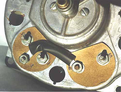
Fuel and Temperature Gauges
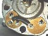
From the passenger side which is left to right in the picture above.
- Fuel Gauge S Terminal - pink wire (from fuel sender)
- Fuel Gauge A Terminal - 12v side of Jumper/Regulator Strip to
temperature gauge
- Fuel Gauge I Terminal - red wire (ignition-on hot 12v)
- Temperature Gauge A Terminal - Jumper from fuel gauge A terminal
(Jumper Strap regulated to 5v)
- Temperature Gauge S Terminal - Purple wire (from temperature
sender)
Some manuals have the positions of these terminals incorrectly
identified. You can see the letters stamped in the insulation
material around the posts.
The Jumper/Regulator Strap is composed of two strips of metal that
continuously make and break contact, regulating the output to the
Temp gauge to 5 volts. A volt meter applied to the A terminal on
the Temp gauge should fluctuate (plus and minus) near 5 volts.
A reading of 12 volts on the temperature side indicates
a bad Jumper/Regulator Strap. 12 volts applied to the temperature
gauge's A terminal will cook the gauge.
Fuel Gauge
The fuel gauge should have the following resistances ...
- S to Ground 68-72 ohms
- S to I 19-21 ohms
- S to A 19-21 ohms
- I to A Zero
- I to Ground 49-51 ohms
- A to Ground 49-51 ohms
The fuel sending unit wires are located on top of the gas tank
where they are hard to get to without dropping the tank.
The fuel sending unit should have a pink wire with voltage on
the isolated center post. The other black wire on the sending
unit with a tab style connector is a ground to the frame.
Make sure it has good contact.
To be sure the problem is not the gauge, you can momentarily short the
pink wire on the output of the sender to ground, and this should show
up as FULL on your gauge. DO NOT hold it for very
long in this position. If the gauge does not move from EMPTY either
the wiring has an open circuit (no voltage, or no connection to ground)
or he gauge is bad. If it does move, the sending unit is bad.
The sending unit can be checked with an ohmmeter to measure the
resistance between the round sender post (pink wire) and ground.
It should be:
| Resistance | Reading |
|---|
| 73 ohms | Empty |
| 23 ohms | 1/2 tank |
| 10 ohms | Full |
If the resistance falls in this ballpark (depending on how much gas
you have in the tank), then the sending unit is fine. If it shows
infinitely HIGH resistance, then the sending unit could be bad OR
the wire from the tank to the gauge could be open.
The gauge can be tested with the resistances listed above. Run
an appropriate resistor to the S terminal of the fuel gauge and
to ground and check the readings.
Temperature Gauge
The temp gauge has the following resistance ...
A volt meter can be used to measure the voltage between the A terminal
of the Temp gauge and ground. It should be pulsing and averaging about
5 volts. If it reads 12 volts the Jumper Strip/Regulator is bad.
If it reads 0 volts, it has been burnt out.
The sending unit can be checked with the following resistances between
the post and ground...
| Totally Cold | high resistance |
| Slightly Warm | 73 ohms |
| Beginning of Band | 36 ohms |
| End of Band | 13 ohms |
| Hot | 9 ohms |
If an appropriate resistor is connected to the S terminal of the
temperature gauge and to ground, the above restances can be used to
check the gauge. Use a resistor close to the specifications
above to simulate the sending unit.
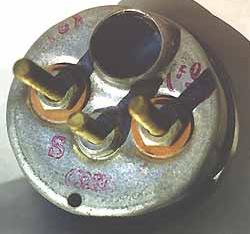
Oil Pressure Gauge
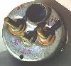
From the passenger side, left to right in the picture..
- Oil Pressure gauge S terminal (left) - Purple wire from sender
- Oil Pressure gauge middle terminal - Black wire (Ground)
- Oil Pressure gauge right terminal - Red wire (Ignition-on hot 12v)
The oil pressure sending unit is on the engine block and looks like a
small 2 X 3 inch filter with one terminal. There may be another sender
plumbed in the same area that has two connectors. It is an oil pressure
switch that is supposed to close below 4 psi to activate a dash warning
light in some speedometer clusters.
To be sure the problem is not the gauge, you can momentarily short the
wire from the output of the Sender to ground. If there is no
resistance, your gauge should read 80 psi. DO NOT
hold it for long in this position. If the needle does not move from
zero psi then, either the wiring (open circuit) or the gauge is bad.
If it does move, the sender unit is bad.
It is very common for the sending units used with the 258 and 232
engines to be inaccurate. Make sure you have a good connection to
the sending unit.
It is easiest to test the sending unit by temporarily plumbing in
a good mechanical gauge.
| Pressure (PSI) | Resistance (ohms) |
|---|
| 0 | 234-246 |
| 20 | 149-157 |
| 40 | 100.5-105.5 |
| 60 | 65-69 |
| 80 | 32.5-34.5 |
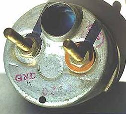
Volt Meter
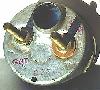
From the passenger side, left to right in the picture ...
- Volt Meter gauge GND terminal (left) - Black wire (Ground)
- Volt Meter gauge terminal (right) - Red wire (Ignition-on hot 12v)
Testing the voltmeter is easy, you just need a good 12 volt connection
to the (+) post and have a good ground to the (-) post. If the
gauge shows no activity, then the gauge is bad.
Conclusion
Many thanks to all those who contributed to this article. Use this
information and your Jeep at your own risk.
|